
Hawk GUI: Channel Config Options
The Main tab consists of the following columns.
| Field name | Description | Editor type |
| Primary Name | Primary name for channel | Free text Drop down selection for speed channel |
| Secondary Name | Alternative name the channel can be known by | Free text |
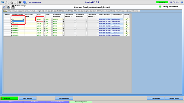
| Type | Channel type | Selected from a drop down combo box listing the channel types. Select “SHAFT” for speed channels. |
| Units | The engineering unit (EU) for the channel | Selected from a drop down combo box listing the units defined (for the current channel type) in the Unit preferences page |
| Calibration Methods | Click on the Calibration method for more information. | mV/EU, DC Calibration, AC Calibration, Facility Calibration, Shunt Calibration, Manual Calibration
|
| Last Calibrated | The date and time the channel was last calibrated | Not editable, automatically filled in. |
| Calibrated By | The name of the user that last calibrated the channel | Not editable, automatically filled in. |
| Enabled | See Channel Settings |
Signal Bandwidth/Net Bandwidth
In the other settings tab, it is possible to overwrite the general bandwidth set in the general configuration page for each channel.

Signal bandwidth defines the sampling rate (sample rate = signal bandwidth * bandwidth factor) of the acquisition card. The sampling rate is the same for all the channels of a given acquisition card, so the signal bandwidth entered will be applied to every other channel belonging to the same acquisition card.
Net bandwidth defines the sample rate of the data that will be recorded to disk and monitored in real-time. Net bandwidth = Signal bandwidth / downsample factor, where downsample factor can be 1, 2, 4,8,16 or 32. The downsampling (low pass filter + decimation) is done by the Hawk acquisition engine on the acquired data coming from the acquisition card.
Sample Size
The dragonfly card can provide ADC counts in 16 bits or 24 bits resolution. This is configurable as shown below:
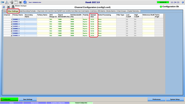
This is also an acquisition card setting, which applies to all the channels on the same card.
A/D Input Range
This is the voltage input range of the A/Ds. This setting is not configurable when using HGL dragonfly acquisition card. In this case it will be set to 10 V (-10V +10 V range), non-editable by the user.
Other Tabs
Other tabs are available in the Channel Configuration page. Those are will be described in later sections of this document. The user has control over which tab are visible in the Channel Configuration, via the preferences:
 Speed Channel
Speed channels are a particular type of channels. To define a speed channel, select “SHAFT” as channel type. For the channel name, chose from a selection of speed channels that have been defined for the current engine.
Frequency Based Tacho
With a frequency based tacho, the revolutions per minute (RPM) of the shaft is a linear function of the measured tacho signal frequency, and will be computed in real-time using the frequency / RPM ratio entered in the engine preferences.
For a frequency based tacho, select “LINEAR” as “calibration method 1."
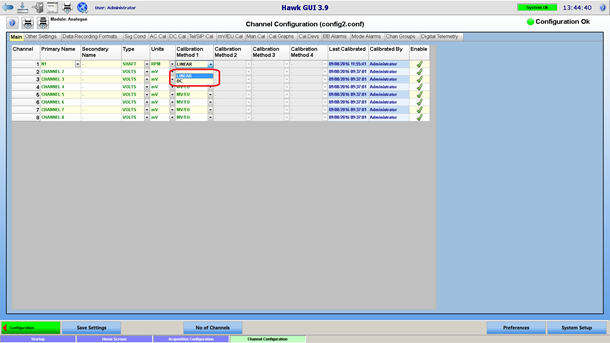
DC Tacho
With a DC tacho, the RPM is a function of the DC level of the raw tacho signal. Such a tacho will be defined by selecting “DC” as “calibration method 1." Then a DC calibration is required, in order to define the relationship between DC level and RPM.
 Flow Channels
Flow channels are setup and processed in the same way as speed channels. To setup flow channels:
- Define flow channels for the engine – sub type
- Optionally, define an alias for base channel type “FLOW”, so you can setup units in relation to the base unit kg/s.
- In the channel configuration page, define the flow channel, with the appropriate calibration method: linear or DC.