Channel Config - CSV Import
Beginning in HawkGUI version 3.10.1.0, the CSV Import option lets users import a CSV file that is not completely populated, or one populated with only the desired information (e.g. channel numbers, channel names, cal type, cal check info, etc). Additionally it uses a separate ini file to "map" column names from your column names to match our expected names.
CSVImportMapping.ini
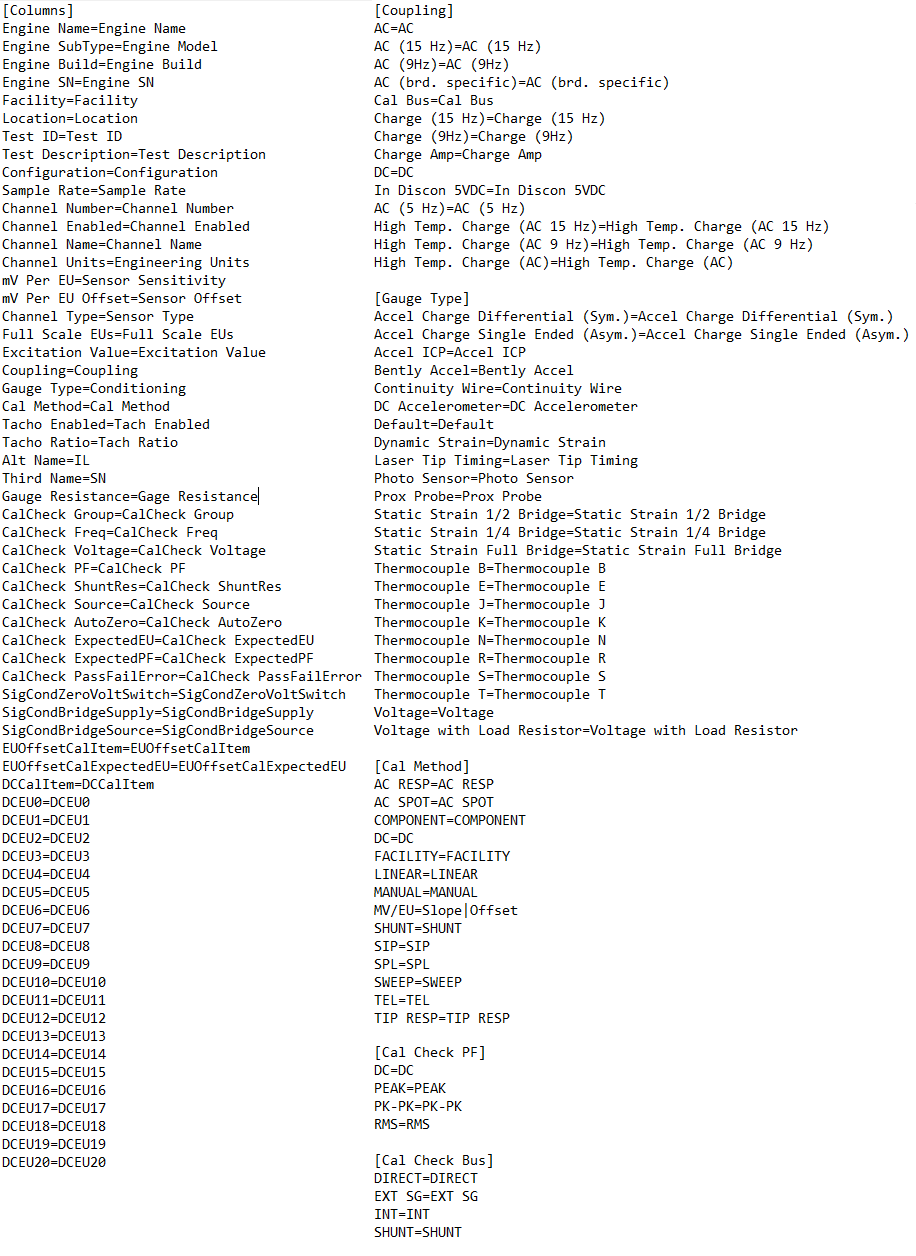
Before you can import CSV files using your naming format, the CSVImportMapping.ini file needs to be configured. The file is located at the following directory C:\HGL Software\settings\CSVImportMapping.ini . The un-configured file looks like the image below. By default, the file largely follows HGL's naming format. If you wish to use HGL's naming format inside of your CSV, this file requires no additional configuration.
Within the file, there are several segments. They are as follows;
- Columns - Changes the names of the column headers in your CSV.
- Coupling - Changes the names of the parameters in the 'Coupling' column of your CSV.
- Cal Method - Changes the names of the parameters in the 'Cal Method' column of your CSV.
- Cal Check PF - Changes the names of the parameters in the 'CalCheck PF' column of your CSV.
- Cal Check Bus - Changes the names of the parameters in the 'CalCheck Source' column of your CSV.
- Sig Cond Zero Volt Switch - Changes the names of the parameters in the 'SigCondZeroVoltSwitch' column of your CSV.
- Sig Cond Bridge Source - Changes the names of the parameters in the 'SigCondBridgeSource' column of your CSV.
Below is a list and description for all of the Column headers and which setting they change within HawkGUI.
[Columns]
*Denotes a per-channel setting
**Denotes a setting that must be pre-defined in HawkGUI, CSV importing doesn't create new entries for these fields
***Denotes a per-channel setting that must be pre-defined in HawkGUI, CSV importing doesn't create new entries for these fields
- Engine Name** - Sets the Engine Name in Acquisition Details.
- Engine SubType** - Sets the Engine Subtype name in Acquisition Details.
- Engine Build - Sets the Engine Build No. in Acquisition Details.
- Engine SN - Sets the Engine Serial No. in Acquisition Details.
- Facility - Sets the name of the Facility in Facility Details.
- Location - Sets the Location in Facility Details.
- Test ID - Sets the Test ID in Acquisition Details.
- Test Description - Sets the Test Description in Acquisition Details.
- Configuration - Sets the name of the Configuration.
- Sample Rate* - Sets a channel's Signal Bandwidth (Hz) in the Other Settings tab. The supplied value should be 2.5 times the desired bandwidth in Hz.
- Channel Number* - Sets the Channel Number in the Main tab.
- Channel Enabled* - Sets if a channel is enabled or disabled in the Main tab. Valid values are TRUE, FALSE
- Channel Name* - Sets the channel's Primary Name in the Main tab.
- Channel Units* - Sets the channel's Units in the Main tab. Valid values are determined by the type of a channel. The following list is all valid values: ACCEL = m/s2, kph/2, G, mm/s2, cm/s2 | DISP = m, mm, um, km, in, cm - IRIG = s | PRESSURE = Pa, KPa, MPa, PSI, KPSI | SPEECH = Hz | STRAIN = uStrain | TEMPERATURE = C, K, F, R | VELOCITY = m/s, in/s, mm/s, kph, cm/s | VOLTAGE = V, mV, kV
- mV Per EU* - Sets the channel's mV/EU ratio in the mV/EU Cal tab.
- mV Per EU Offset* - Sets the channel's Offset in the mV/EU Cal tab.
- Channel Type* - Sets the channel's Type in the Main tab. Valid values are ACCEL, DISP, IRIG, PRESSURE, SPEECH, STRAIN, TEMPERATURE, VELOCITY, VOLTAGE
- Full Scale EUs* - Sets the channel's Gain in the Sig Cond tab. The value in your CSV should be in mV. A value of 10,000mV would be a Gain of 1. 1,000mV would be a gain of 10, 100mV would be a gain of 100, etc.
- Excitation Value* - Sets the channel's Excitation value in mV in the Sig Cond tab. The most common value is 4. This primarily applies to channels set to Accel ICP signal conditioning.
- Coupling* - Sets the channel's Coupling type in the Sig Cond tab. The valid values depend on channel type. By default the possible Coupling values are: AC, AC (15 Hz), AC (9 Hz), Cal Bus, Charge (15 Hz), Charge (9Hz), Charge Amp, DC, In Discon 5VDC
- Gauge Type* = Sets the channel's Gauge Type in the Sig Cond tab. The valid gauge types will depend on what the channel type is. Valid values are: Static Strain 1/4 Bridge, Static Strain 1/2 Bridge, Static Strain Full Bridge, Dynamic Strain, Accel Charge Differential (Sym.), Accel Charge Single Ended (Asym.), Accel ICP, Voltage, Prox Probe
- Cal Method* - Sets the channel's Calibration Method 1 in the Main tab. Valid values are: AC RESP, SWEEP, DC, MANUAL, SHUNT, MV/EU, COMPONENT (Calibration Method 2 isn't manually set, it is automatically set to EU OFFSET if EUOffsetCalItem and EUOffsetCalExpectedEU have supplied values)
- Tacho Enabled*** - Determines if a channel is a Tacho or not. Valid values are TRUE, FALSE
- Tacho Ratio* - Sets the channel's Tacho Ratio.
- Alt Name* - Sets the channel's Secondary Name in the Main tab.
- Third Name* - Sets the channel's Tertiary Name in the Other Settings tab.
- Gauge Resistance* - Sets the channel's Gauge Resistance in the Sig Cond tab.
- CalCheck Group* - Sets the channel's Cal Group in the Calibration Check tab.
- CalCheck Freq* - Sets the channel's Cal Freq Hz in the Calibration Check tab.
- CalCheck Voltage* - Sets the channel's Cal Voltage mV in the Calibration Check tab.
- CalCheck PF* - Sets the channel's Cal PF in the Calibration Check tab. Valid values are PEAK, RMS, PK PK
- CalCheck ShuntRes* - Sets the channel's Shunt Resistance in the Calibration Check tab.
- CalCheck Source* - Sets the channels Cal Source in the Calibration Check tab. Valid values are INT, EXT SG, DIRECT
- CalCheck AutoZero* - Sets the channel's AutoZero in the Calibration Check tab.
- CalCheck ExpectedEU* - Sets the channel's Expected EU in the Calibration Check tab.
- CalCheck ExpectedPF* - Sets the channel's Expected PF in the Calibration Check tab. Valid values are PEAK, RMS, PK PK
- CalCheck PassFailError* - Sets the channel's Pass/Fail Error % in the Calibration Check tab.
- SigCondZeroVoltSwitch* - Sets the channel's 0V Switch in the Sig Cond tab.
- SigCondBridgeSupply* - Sets the channel's Bridge Supply in V when Conditioning is set to Static Strain (1/4, 1/2, or Full), or in mV when Conditioning is set to Dynamic Strain within the Sig Cond tab.
- SigCondBridgeSource* - Sets the channel's Bridge Source in the Sig Cond tab. Valid values are Voltage when Conditioning is set to Static Strain (1/4, 1/2, or Full), or Current when Conditioning is set to Dynamic Strain.
- EUOffsetCalItem* - Sets the channel's Cal Item in the EU Offset Cal tab.
- EUOffsetCalExpectedEU* - Sets the channel's Expected EU in the EU Offset Cal tab.
- DCCalItem* - A number used to group DC cals together with other channels. Ie. if you want to calibrate channels 1 - 4 together they can all be set to DCCalItem 1
- DCEU0 - DCEU20* - These are the DC calibration points, using the channels EU. At least 2 DC EU points must be defined and all points should be consecutive. All channels on the same DCCalItem need to have the same DCEU values.
Configuring Your CSVImportMapping.ini
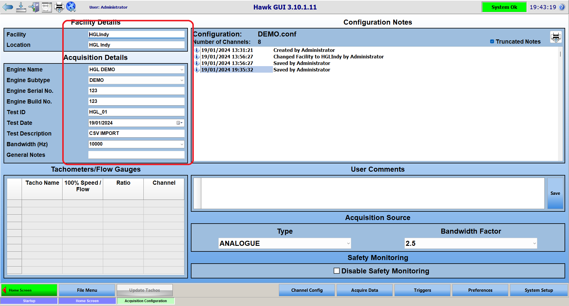
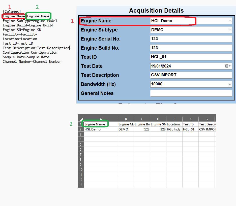
In the figure below, the Engine Name parameter is being used as the example. Inside of the CSVImportMapping.ini file, the 'Engine Name' to the left of the '=', labeled with the red and the number 1, corresponds with a configurable setting in the software. In this case, that is the Engine Name field, located on the Acquisition Configuration screen.
The 'Engine Name' to the right of the '=', labeled with the green and the number 2, corresponds with the column header in the CSV file you are trying to import. In the example, the column header is labeled 'Engine Name', and the name of the engine is 'HGL Demo'. When the CSV file is imported, the software will look for the column header 'Engine Name', and then populate the Engine Name field in HawkGUI with the supplied value, which in this case is 'HGL Demo'.
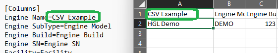
Below is an example of a custom naming format. In this case the software will be looking for the column header 'CSV Example', and will populate the Engine Name field in HawkGUI with the supplied value, which is 'HGL Demo'. When using custom naming formats for column headers, make sure that each one is unique.
CSV File Format
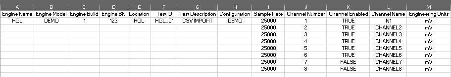
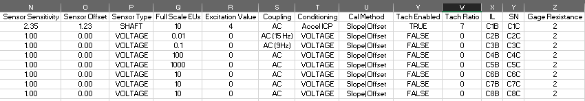
The CSV file will need to use use the naming format for column headers found in your configured CSVImportMapping.ini file. The column header should be placed in row 1 of a given column. The value you want to use should be placed in row 2 of the same column. Some parameters can have more than one value, in that case they should be placed in row 2 of the column, then row 3, then row 4, and so on, until all desired values are present.
Below is an example of a valid CSV file using the default HGL naming format.
Importing From a CSV
To import a config using a CSV file, follow the instructions below.
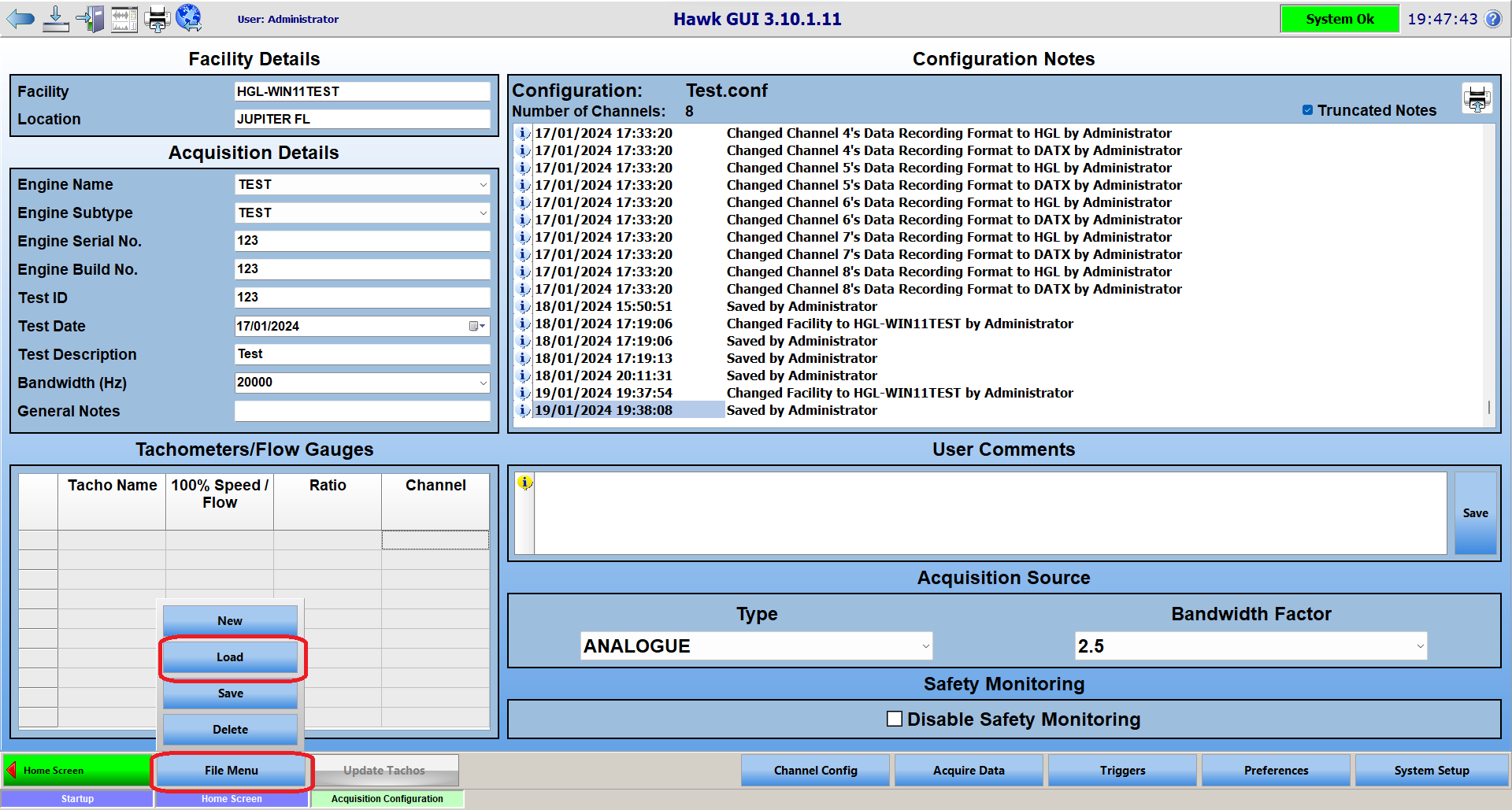
First, click on 'File Menu', then 'Load'.
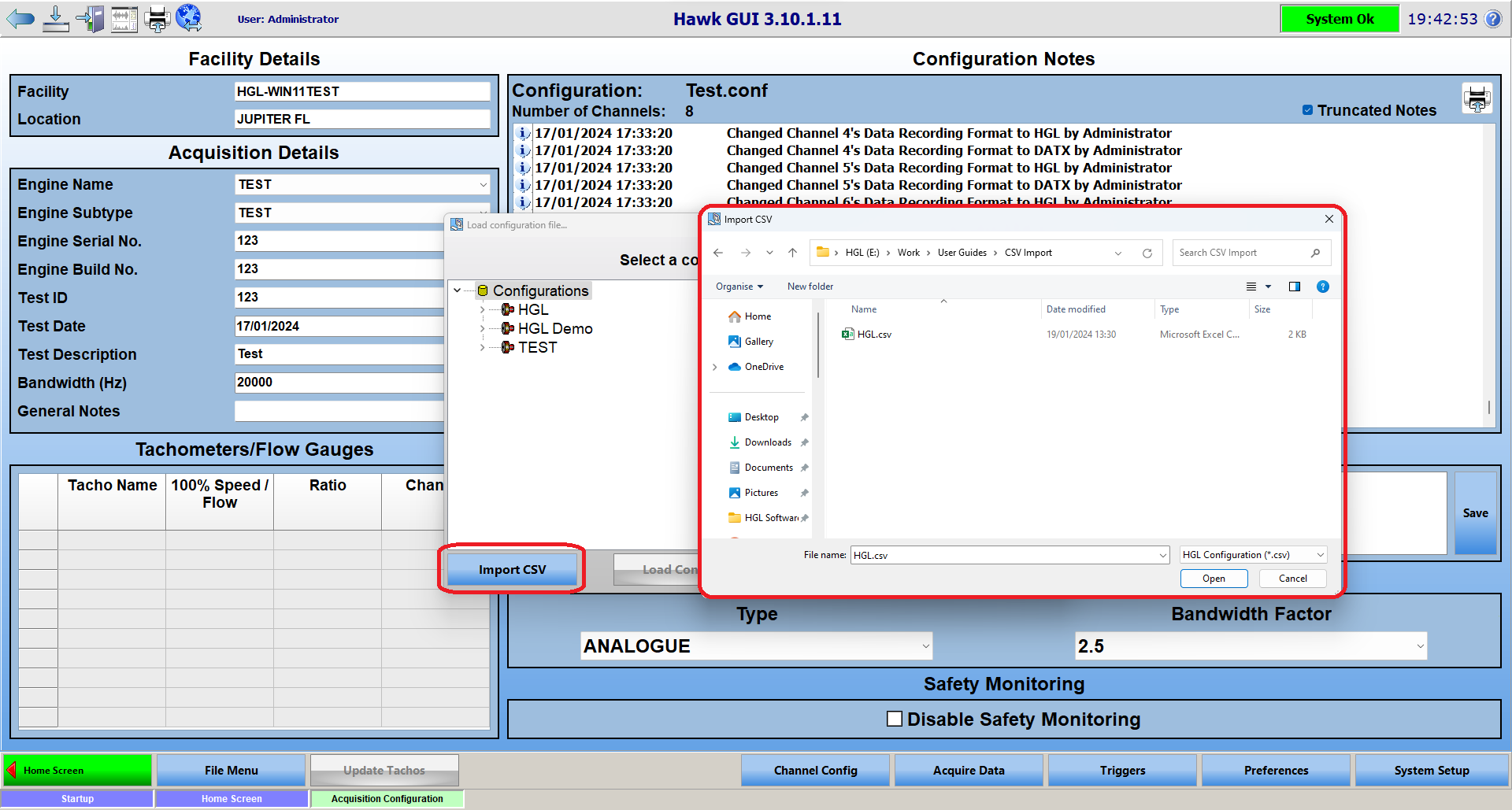
Then click on 'Import CSV', and a file browser window will open. Locate the CSV file you intend to use, select it, and click 'Open'.
Once you click open, it should populate HawkGUI with the settings found in your CSV file. Once the config has been loaded, it is recommended that you click 'File Menu' and then 'Save'. If you forget to, HawkGUI should prompt you to save the imported configuration prior to leaving the Acquisition Configuration page.