
Calibration Test Unit Operation
Calibration Test Unit Overview


PLEASE NOTE: If you have a CTU V2 as pictured above, please use this updated article.
HGL Calibration Test Unit (CTU) is used in combination with the HGL Dragonfly STU software program.
The CTU is able to simulate most of the signals that are conditioned by the Hummingbird and Dragonfly acquisition modules. This includes:
- Voltage (All gain ranges)
- Charge (single ended and differential)
- Dynamic Strain (120 Ω, 350 Ω, and 1000 Ω)
- Bridges (Full, Half, Quarter; all gage types)
When the CTU is not used to calibrate the acquisition hardware, the built in Cal Bus can be used to perform a voltage calibration on the Hummingbird with the caveat that the signals can get attenuated from loading. Dragonfly modules without a Cal Bus can be calibrated by connecting directly to all eight analog inputs.
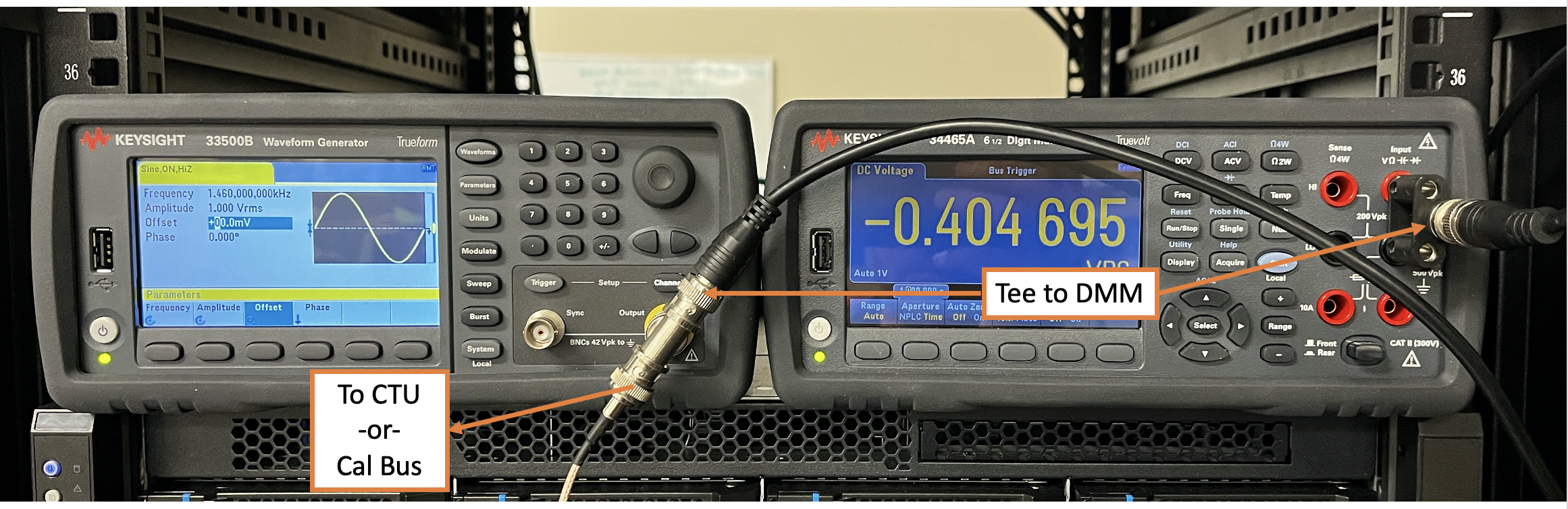
Calibrating an acquisition module also requires using a Keysight (or Agilent) Arbitrary Function Generator (33500B Series) and 6.5 Digit DMM (34465A) with networking capabilities.
Using the CTU and Calibration software require V4 Dragonfly use CPU firmware version 2.53 / FPGA 5.12 or be a V5 Dragonfly systems. It is not compatible with V2 or V3 Dragonfly systems.
System Wiring
The CTU lives on the BLACK network when connecting it to the host calibration PC. Best option is to connect the CTU and Hummingbird / Dragonfly to a switch that the calibration PC is on. The Calibration PC cannot currently be on a network (GREEN or BLACK) with a Hawk System since it will rebroadcast messages that causes the Calibration Software to lock up. Use the HGL Acquisition Terminal to confirm communication with devices or to change device IP Address using the multicast.
PLEASE NOTE: Disconnect analog cables between the Hummingbird and CTU before removing power from the units. Failing to do so may result in your CTU needing to be repaired.
- Connect the networks for the CTU, Hummingbird / Dragonfly, and Calibration PC on the BLACK network using an external switch. V4 Hummingbird can work on the CTU Switch. V5 modules have larger messages and can swamp the switch.
- Connect the networks for the Signal Generator and DMM to the Calibration PC on the GREEN or other spare network.
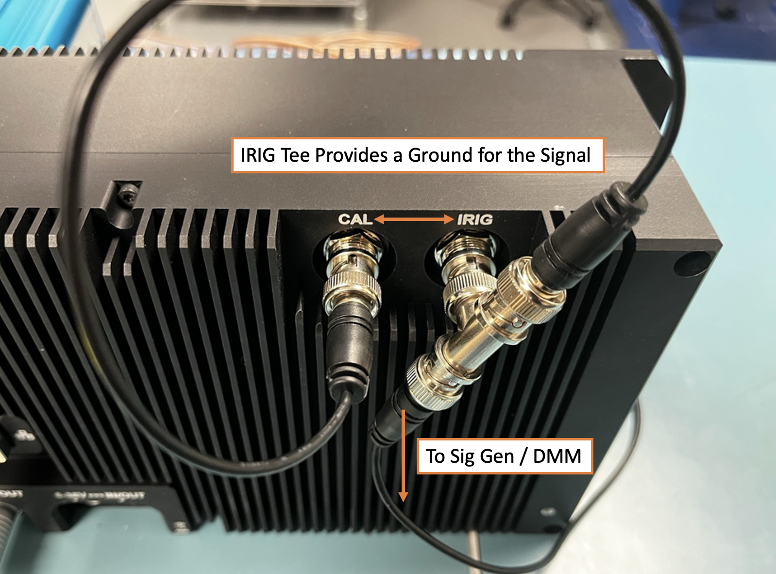
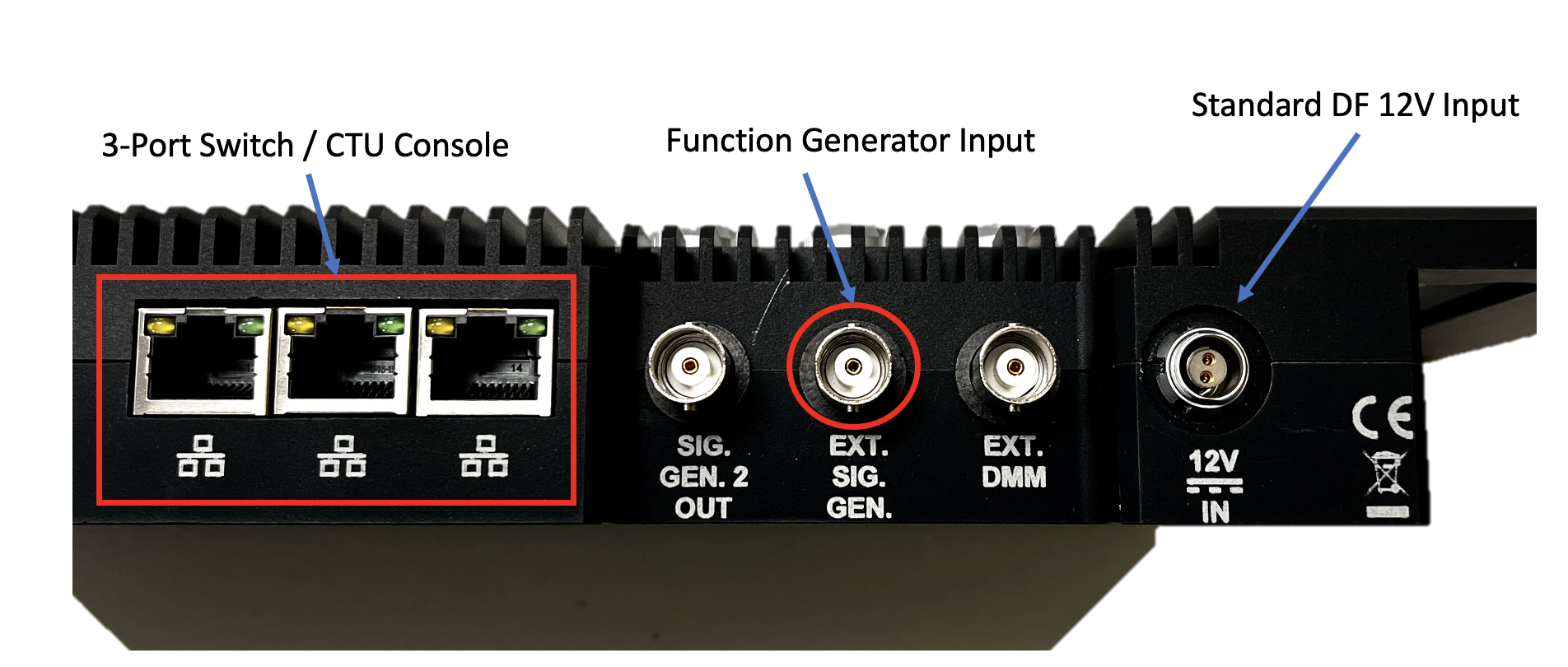
- Connect the Tee'd Signal Generator / DMM to the "Ext Sig Gen" BNC on the CTU.
- If a CTU is not used, connect to the "CAL BUS" on the Hummingbird with a second tee between the IRIG BNC and the "CAL BUS" BNC.
- Connect the CTU Outputs to the Dragonfly or Hummingbird inputs.
- Hummingbird32 can take all 32 inputs.
- Hummingbird48 only calibrates the first 24 OR second 24 channels at one time.
- Depending on the Hummingbird and CTU unit, it is necessary to rewire the calibration setup.
- 18C Amphenol Hummingbird to LEMO CTU requires changing cables. Voltage, Full+Half Bridge, and Quarter Bridge all use a different cable set.
- 18C Amphenol Hummingbird to 18C Amphenol does not require cable changes.
- LEMO Hummingbird to LEMO CTU does not require cable changes.
- For a Dragonfly Module and no CTU, directly Tee the Signal Generator output to all 8 analog inputs. Networking Configuration is unchanged.
Setup DMM and Signal Generator Networks
The DMM IP Address and Signal Generator Address is specified in the HGLDragonflySTU.ini file using the fields:
"CTU Output DMM Address"
This is only used for the measuring the CTU outputs.
These settings can also be changed from the application in the Preferences settings.
HGL Dragonfly STU Preferences
The preferences are defined by an INI file or also accessible via the application GUI. To get to the preferences, the system does need to be working else it can crash when loading, so there are times when the preferences can only be changed from the INI file. The STU Software has different modes of operation depending on what hardware is being calibrated.
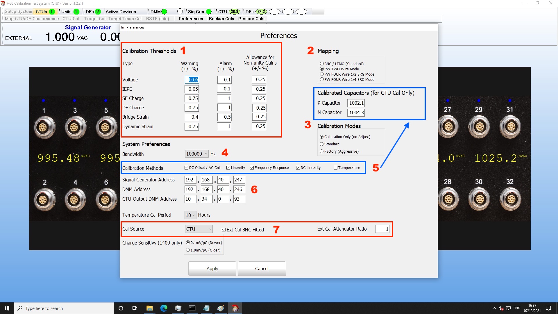
- Calibration Thresholds: This section is only used for the Conformance tests. Currently actual calibration thresholds for making adjustments is hard coded.
- Mapping: Selection option to required when calibrating Hummingbird units with the 18C analog inputs. This requires changing the cables to match the functions that will be checked or calibrated.
- Calibration Mode:
- Calibration Only is a Verification run.
- Standard is a three pass calibration run. The first two passes will make adjustments. The third pass will not make any adjustments
- Factory performs up to six passes and makes adjustments after each pass except the last.
- System Bandwidth: Always set to 100000 Hz
- Calibration Methods and Calibrated Capacitors are only used when calibrating the CTU.
- This is where the IP Addresses for DMM and Sig Gen that are used with the CTU are specified. Dragonfly and CTU modules are automatically detected on the BLACK network.
- Cal Source:
- Either CTU or Cal BUS
- Un-Check Ext Cal BNC Fitted when calibrating a standard 8 channel Dragonfly Module
- Ext Cal Attenuator Ratio is used for older Agilent Signal Generators that cannot output lower than 10 mV RMS requiring an inline 0.8 Attenuator to be fitted.
HGL Dragonfly STU Operation
The CTU and the Hummingbird or Dragonfly being calibrated are required to be on the same network range. Use HGL Acquisition Terminal to check IP Address and other settings to confirm communication. It is not recommended to use the CTU switch with a 24/32 Channel V5 unit.
Make sure that all devices required for calibration are powered on before starting the HGL Dragonfly STU executable.
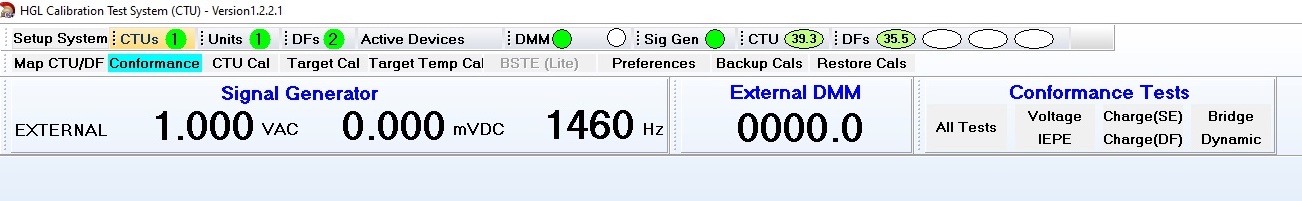
When the software launches, users are presented with simple interface and will need to setup the system.
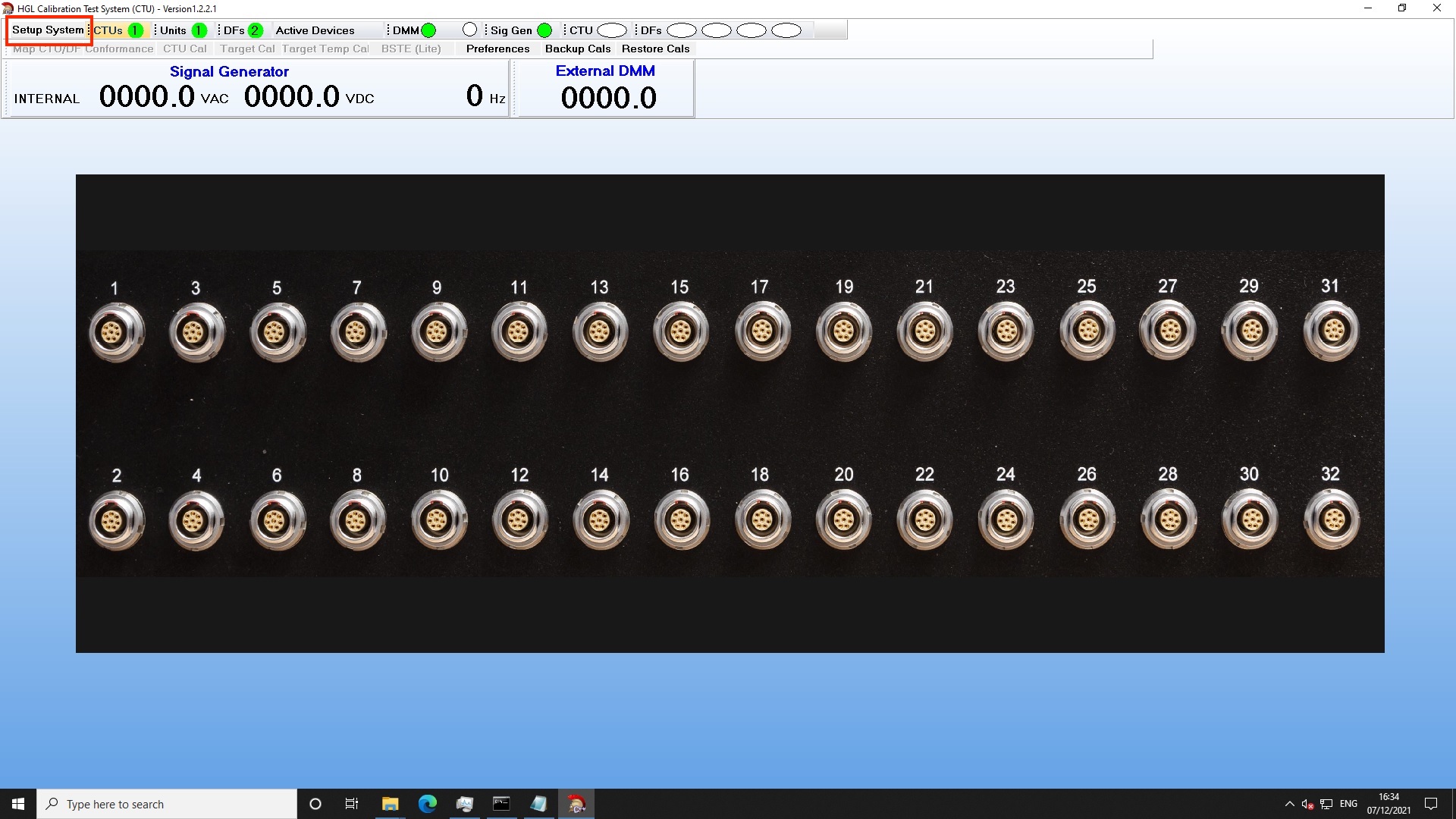
At the top of the window there are GREEN circles that indicate the presence of each component the STU detects. Numbers in the GREEN circles indicates the quantity for each type. The exception is for DMM which will have a second GREEN circle when two can be detected. Verify that both a Sig Gen and DMM have a GREEN circle.
Click the "Setup System" text and a window will pop up showing the available devices. The units are separated by type with any CTU units being on the far left, the middle will have any complete Hummingbird listed, and the right column will list all Dragonfly or Hummingbird cards regardless of if they are in a parent device. If the Parent device is configured correctly, simply select the "Unit" to calibrate. If it is a Hummingbird 48, it is necessary to calibrate each half at a time. If it is a Dragonfly module, it will only be on the right hand column.
Select "CTU Only" mode if calibrating the CTU or using it as a simulator. Select "Ext Cal Only Mode" if using a Hummingbird or Dragonfly without a CTU in the setup. "BSTE Mode" is not commonly used.
 Once the devices have been selected, click "Start". If any devices in the Setup need to change, it is necessary to restart the application.
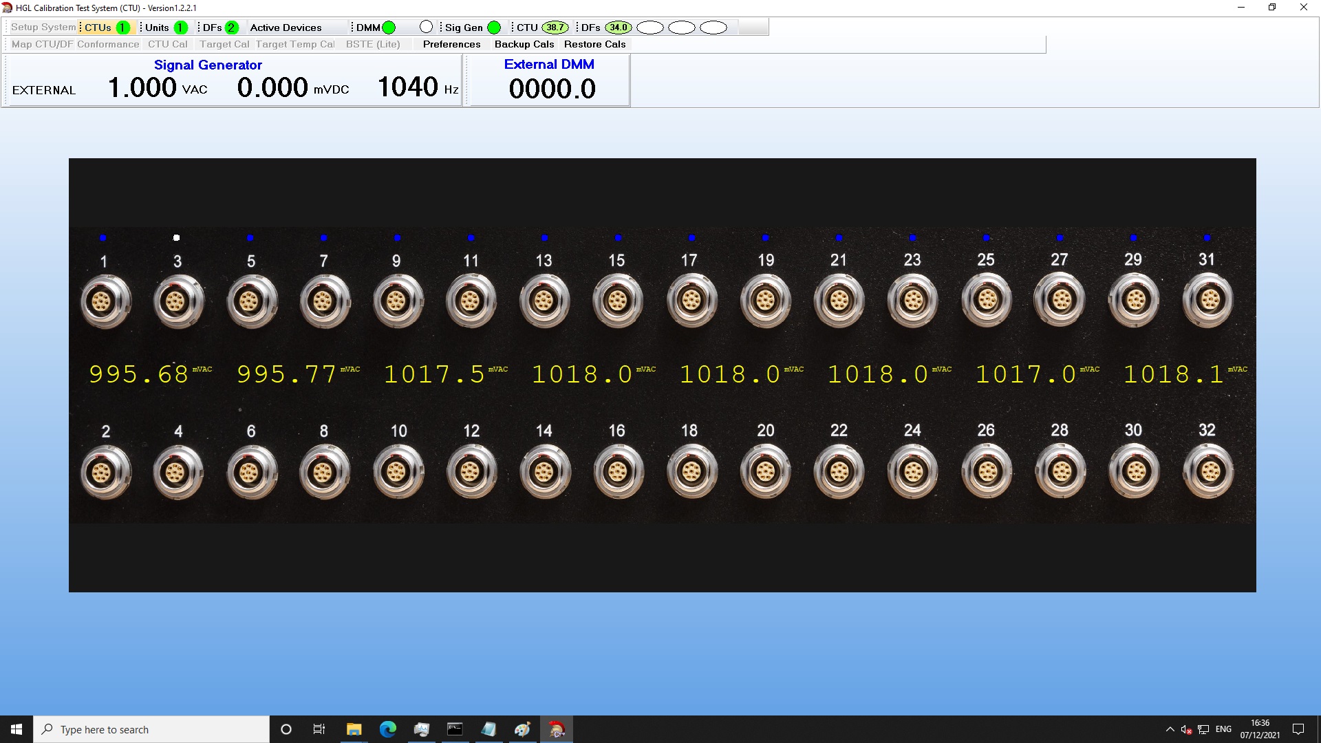
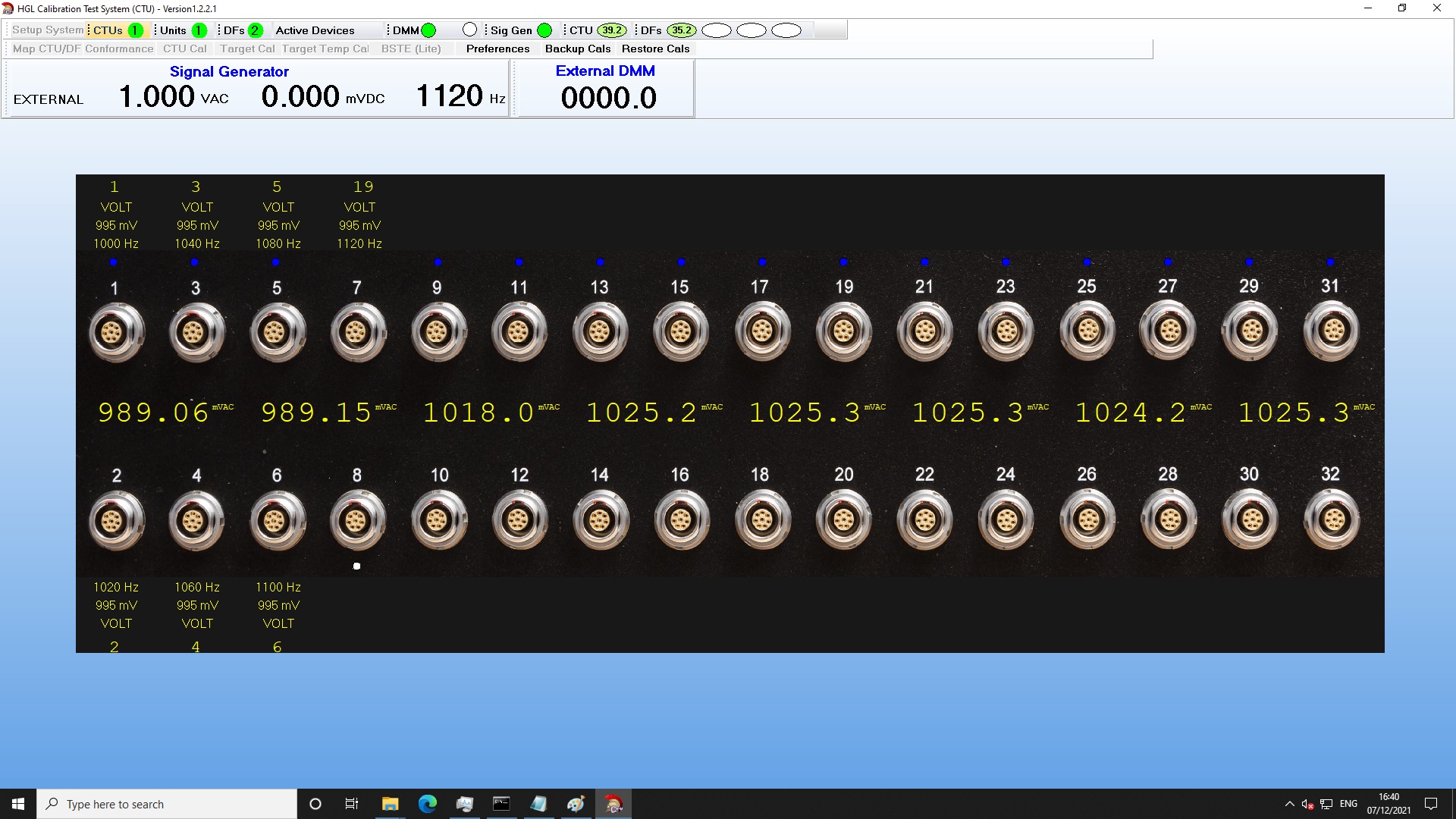
There will be a brief pause while the software establishes communication with the different devices. When this completes, there will be values in the ovals next to CTU and DFs that reflect the onboard temperature reading of each component in the system. If these go blank during a calibration, it means that the STU software temporarily lost comms with that device and it needs to restart. This sometimes requires using "End Task" from the task manager.
If a CTU is being used, it will automatically start mapping the channels by using a frequency from each output and measuring that on the acquisition device to confirm the channel location. It is possible for this to have a fault on the first iteration (e.g. not detect a connect channel or put it in the wrong location). Click the "Map CTU" button and try again. If this fails, restart the STU software. A successful mapping will have the channel number of the CTU over the channel of the Hummingbird picture with a frequency displayed. A white dot on top of the channel means that channel is active. Blue dots are channels not active. The V1.5 CTU is limited to 16 channels working simultaneously.
The two calibration modes that are used once the system is ready are: Target Cal and Conformance. Target Cal updates the calibration values of the Hummingbird based on the mode of operation (Verification, Standard or Factory). Conformance checks the signal conditioning operations. Click the name for each mode to view the different options available.
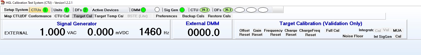
Target Cal will show all of the calibration values to be Verified/Adjusted or Reset:
- DC Offset
- Gain
- Frequency
- Charge (requires CTU)
- Charge Frequency (requires CTU)
- Internal Sig Gen
The Conformance mode requires the CTU and lets all the types of conditioning to be checked. For the 18C Hummingbird, it is necessary to change the cables between different types of Bridge conformance checks.
Target Calibration
Target Cal is used to update the calibration values stored in the Hummingbird and Dragonfly memory. There are two separate amplifier paths in the signal conditioning. One is for standard voltage signals which covers IEPE, Bridges, and Dynamic Strain. The second path is for the charge amplifier. These are calibrated using one of two methods: direct input into the each channel using the CTU or a Signal Generator or routing signals through the Calibration Bus.
Notes regarding using Cal Bus: The cal bus is known for the input signals being attenuated. Also, it is necessary to tee the signal generator input to the IRIG BNC to make the input single ended. Finally, charge calibration cannot be performed using the cal bus.
Performing a full calibration each year is not always required. HGL recommends putting the calibration software in verification mode first and check the results. The frequency calibration should only need to be performed from the factory - if there is significant deviation in the results, contact HGL. Minor frequency response variation of 2-3% is acceptable for daily operation and may be found in the high frequency range. This will vary between conditioning cards as some are only designed for 0- 80 kHz bandwidth.
If the Offset and Gain are outside of the expected values, change the calibration mode to "Standard" and run Offset and Gain in order. Each test will take up to 3 passes to complete (Check and Adjust, Check and adjust, verify).
HGL's Acquisition cards support calibration values for:
- AC / DC Offset values per gain stage
- AC frequency response per gain stage
- AC / DC offset values for a temperature sweep referenced to the internal temperature reading
- Single and Differential charge values per gain stage
- Single and Differential charge frequency response per gain stage
- Noise Floor measurements
- AC / DC Offset Cal Bus adjustment (no specific calibration standard applied as this is just for reference
The Target Calibration should be performed in order from Offset to Gain to Frequency. Click on the name of each method to start the calibration. Each type of calibration values can also be reset by clicking the "Reset" button under each main calibration method name. If using a CTU, then proceed with calibrating the Charge methods.
Reports are saved into a folder on the C drive of the computer in a sub directory for each calibration type. The results are in a time-stamped CSV file with the stated tolerances currently being hard coded to tight tolerances.
Conformance Test
Verifying the signal conditioning operation programmatically using the HGL Dragonfly STU requires the CTU. The CTU simulates all the different signal conditioning methods that are supported by HGL's acquisition hardware. The conformance tests do not result in any calibration changes to the acquisition hardware. These are strictly used to confirm operation and large variances can indicate an issue with the unit, grounding, or cables.
The available conformance tests are:
- Voltage
- IEPE
- Charge (SE)
- Charge (Diff)
- Bridge (tests Quarter, Half, and Full; all resistances)
- Dynamic Strain (tests all resistances)
Results are output as a PDF file in a directory on the C Drive.