Channel Config: Virtual Channels
It is possible to define additional channels in the configuration, which are the result of an operation performed upon one or more source channels. Those virtual channels
- will be assigned channel numbers in the configuration,
- will be displayed in the HawkEye real-time display,
- will be recorded to disk in the format of choice,
just like any regular channel.
The source channel(s) of any virtual channel must be acquired by the same Hawk acquisition engine. The resulting virtual channel will be computed by the Hawk owner of the source channel(s).
For any given Hawk, the virtual channels can be defined at the end of the Hawk’s channel range. For example, if Hawk#1 is attached to 2 acquisition devices of 32 channels each, and therefore has 64 acquisition channels, the user may setup some virtual channels on that Hawk, from channel number 65 onwards. Therefore, if a second Hawk#2 starts at channel 65, Hawk#2 will have to be shifted up in order to make some room for some virtual channels on the Hawk#1. For example, the user may move the Hawk#2 start channel to 80, leaving space for 15 virtual channels (channel 65 to 79) on Hawk#1.
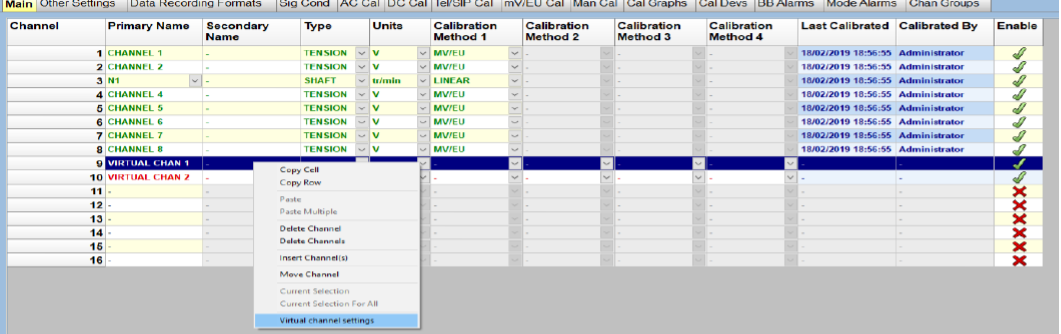
In the example below, we have a single Hawk attached to a single dragonfly device (channel 1 to 8). The user may click on any channel, in any column, and select the “Virtual channel settings” option.
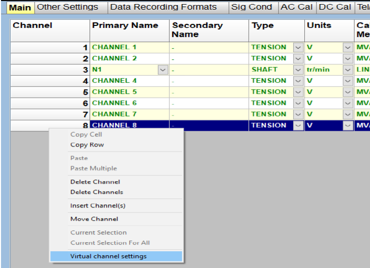
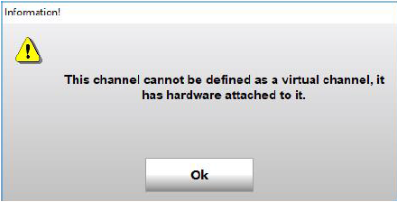
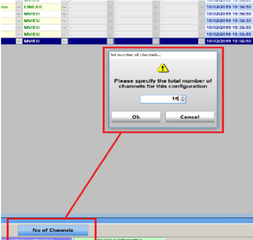
In the example above, the user has clicked on channel 8. Channel 8 being a genuine acquisition channel, it cannot be defined as a virtual channel. The following message will therefore appear on the screen:
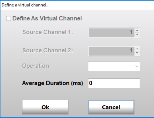
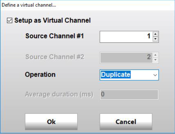
Subsequently, the virtual channel setup dialog will be displayed with the option to “Setup the channel as virtual” disabled, as shown below:
Pursuing on the same example, the user may increase the number of channels to 16, by clicking on the “No of Channels” button in the navigation bar.
The additional 16 channels, not being attached to any hardware, may be enabled and defined as virtual channels. The user will give them a name, like any regular channels. The other channel information may not need to be filled in; this will depend on the type of operation. In our example, two virtual channels have been named and enabled, channel 9 and 10.
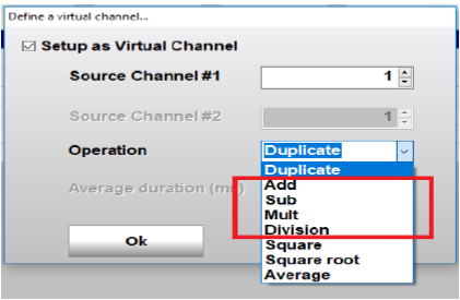
The user may now define the operation on channel 9, as shown below:
Channel 9 is allowed to be a virtual channel, because there is no hardware attached to it. So the virtual channel setup dialog will be enabled, and the user can tick the option “Setup as a virtual channel”.
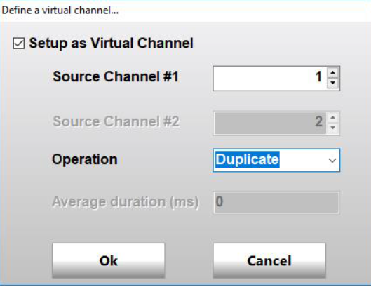
Various operators are available (menu Operation), requiring a single or two source channels (boxes Source Channel #1 and #2). The following section goes through the various operators available.
Channel Duplication
The “Duplicate” operator is a unary operator, in other words it takes a single source channel as operand. The raw samples from the source channel will be duplicated, but the duplicate channel will have its own calibration. Raw data will be recorded with the same resolution as the source channel, but the user may define a different net bandwidth than the source channel. Having its own calibration information, the duplicate channel will have its own channel type and units, as well as calibration method.
The duplicate channel will not appear in the signal conditioning tab, as it will share the same conditioning setting as the source channel. During acquisition, any gain change occurring on the source channel will also be recorded against the duplicate channel.
The dialog below shows how to setup channel 9 as the duplicate of channel 1. Note that the average duration setting is not applicable with this operator. In fact, the average duration setting is only applicable if “Average” operator is selected.
User may validate the choice by clicking on the Ok button. Channel 9 will now be displayed as being the copy of channel number 1. User will then need to define the other fields for that channel, including calibration method, just like any regular channel. In our example, channel 9 is not fully setup, and is therefore displayed in red. So is channel 10, for which we have not defined yet the operator and operands.

Other Binary Operators
“Add” / “Sub” / “Mult” and “Div” operators perform sample by sample operations between 2 source channels For each pair of matching samples, the operation is performed on the calibrated samples, producing a floating point sample as a result. This is why, in the other settings tab, the sample size of the virtual channel will be greyed out, and set to “Float”, meaning single precision IEEE float. During writing, such a virtual channel would therefore be recorded in floating point data, in HGL file format or DATX file format.
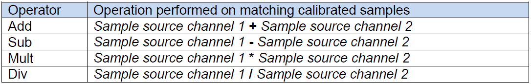
The table below summarise the various operations:
Those operations require both source channels to be at the same net bandwidth. Failing that, there will be an error when trying to configure the system. The virtual channel produced will have the same bandwidth as its source channels.
For “Add” and “Sub”, both source channels must have the same channel type and acquisition unit, and the resulting virtual channel will share the same channel type and units than its sources. For “Mult” and “Div”, there is not such a constraint, and the user will define the channel type and units of the virtual channel. For the “Div” operator, if a sample of source channel 2 is 0, the operation is invalid, and the resulting sample for the virtual channel will bet set to 0.
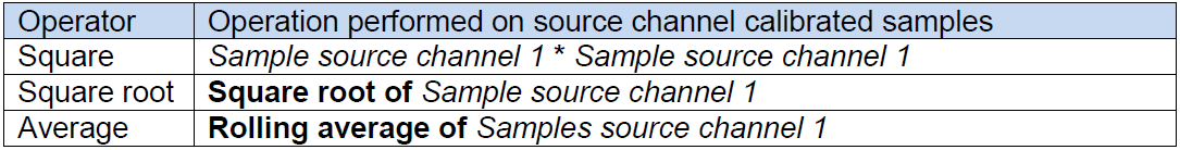
Other Unary Operators
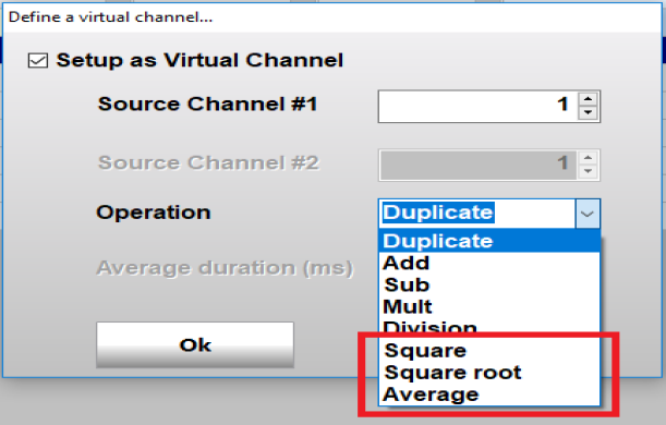
For the square and square root operators, the user will define the channel type and units of the virtual channel.
For the square root operator, if the sample of the source channel is < 0, this is an invalid operation, and the resulting sample for the virtual channel will be set to 0. The average operator will perform a rolling average of the samples of the source channel. The user will define the average duration in milliseconds, which will be converted to a number of samples based on the sample rate of the source channel.
The table below summarise the various unary operators: