
Hypersonic Wind Tunnel Acquisition Mode
Before Hypersonic Wind Tunnel mode can be used for acquisition a channel of type 'Trigger' needs to be created.
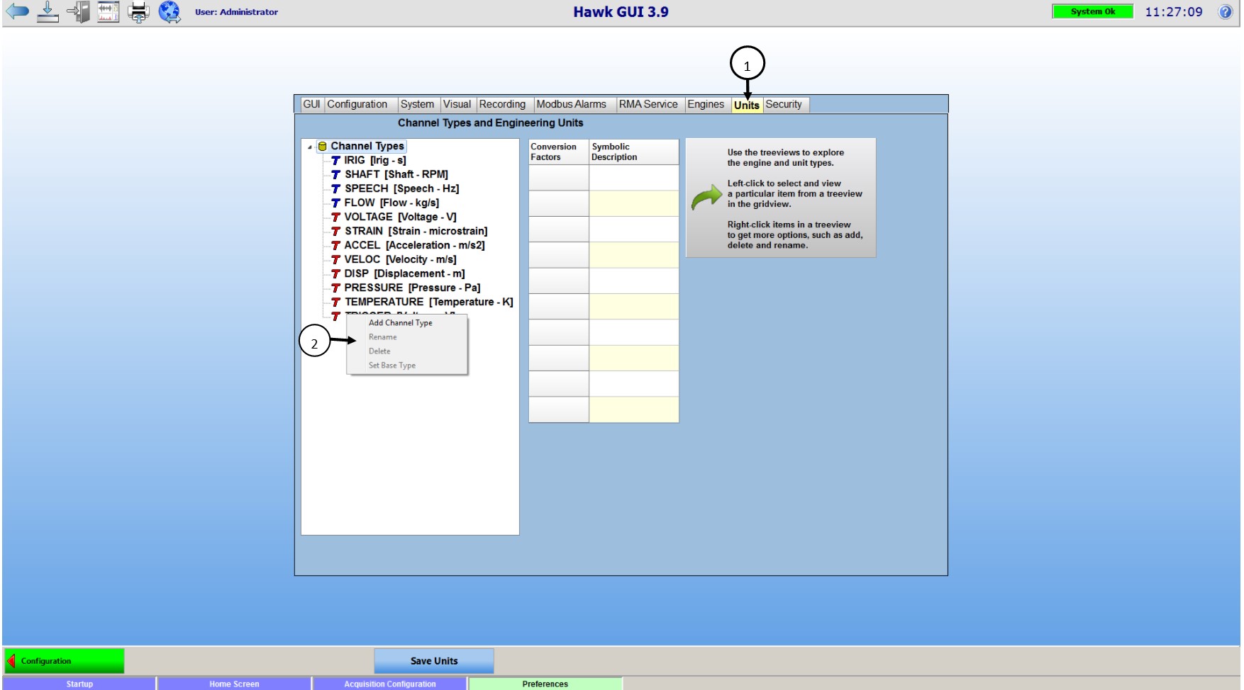
- Click 'Preferences' from the Hawk GUI screen
- Go to the 'Units' tab (1 in the picture below)
-
Right Click in the 'Channel Types' pane, from the drop down select 'Add Channel Type' (2 in the picture above)
-
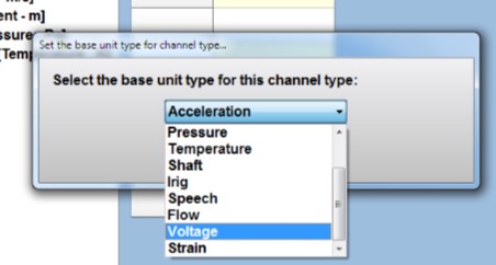
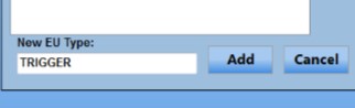
Below the 'Channel Types' pane a text field will appear, enter the word 'TRIGGER' and select base unit type 'Voltage'
-
Double click on Symbolic Description and enter 'TRIG'
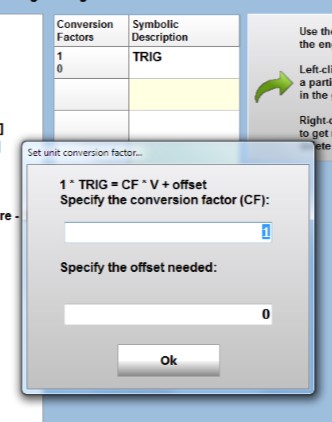
- Right click under Conversion Factors and enter 1 under 'Specify the conversion factor' and 0 under 'offset needed' and select ok
- Save units at the bottom


Once the channel type 'Trigger' is available, it needs to be added to the channel configuration.
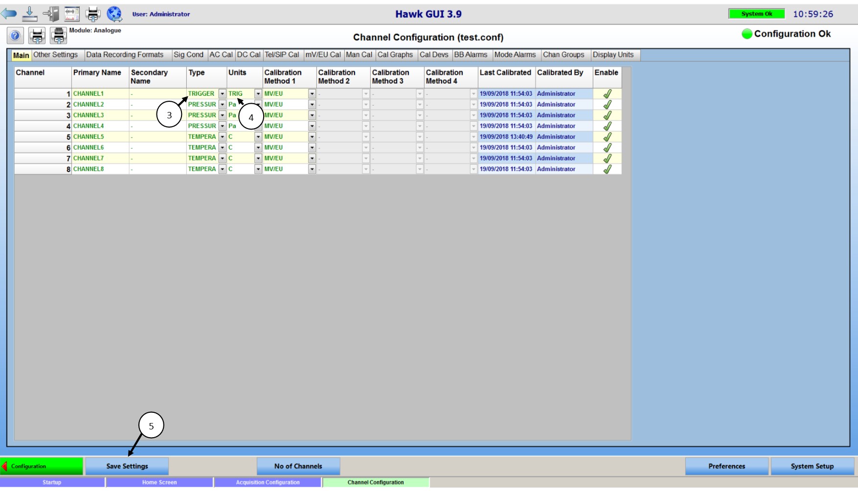
- From Hawk GUI's configuration page, go to Channel Config
- Determine which channel of the configuration will be used for the trigger
- Set the channel being used to having a type of 'TRIGGER' by using the drop down
- The 'Units' field should automatically update to show 'TRIG'
- Save settings and return to the configuration page
With a trigger channel created we are now able to use Hypersonic Wind Tunnel Mode. On the first run of Hypersonic Wind Tunnel Mode we need to set the parameters for the trigger.
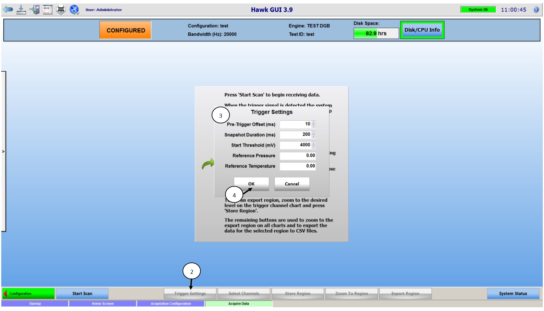
- From the configuration page in Hawk GUI select 'Acquire Data'
- Once the system is configured, you will see 'Trigger Settings' on the bottom menu
- The Trigger Setting menu will appear
- Pre-Trigger Offset (ms) - Length of data kept before the trigger was seen in milliseconds
- Snapshot Duration (ms) - Length of data kept after the trigger was seen in milliseconds
- Start Threshold (mV) - Voltage level at which the trigger will trip in millivolts
- Reference Pressure - A known pressure used for reference
- Reference Voltage - A known voltage used for reference
- Once the settings are finalized select OK
With the trigger channel in the configuration and the trigger channels parameters defined we are ready to start scanning.
![]()
- Select 'Start Scan', the system status will now display 'Scanning' with a green background
- Once the system has triggered, it will say 'Collating Data', once data is ready the system will prompt the user to select which Pressure and Temperature channels. Click Accept Channels.
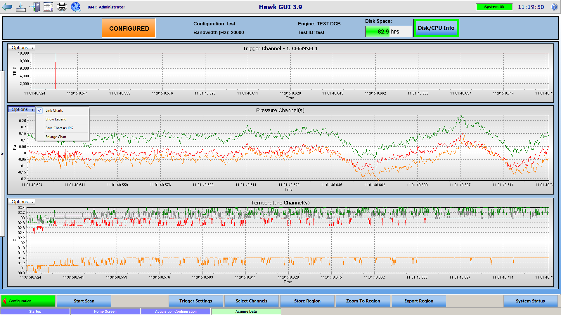
- The data will appear on the following screen with the Trigger Channel on Top, Pressure Channels in the middle, and Temperature Channels on the bottom

Options
- Zoom-In on any plots time domain by clicking and dragging the right mouse button to the right highlighting the region of interest, the amplitude will auto scale.
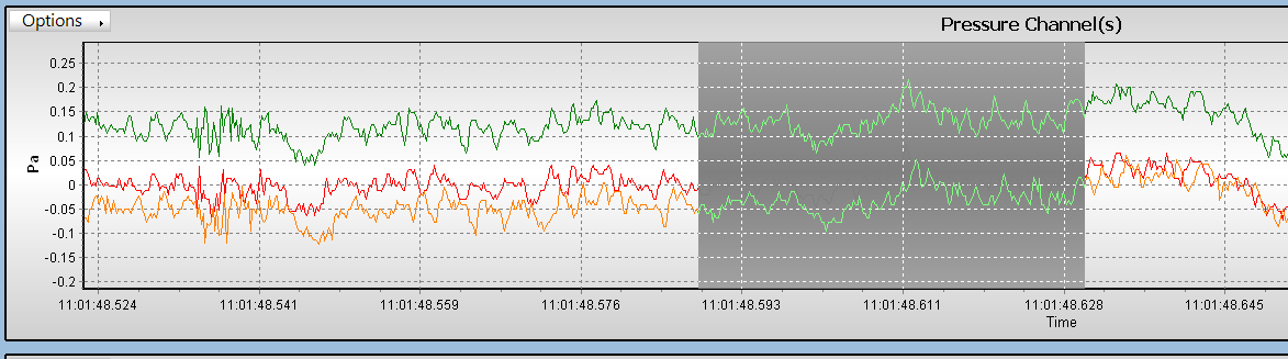
- Zoom-Out on any plots time domain by clicking and dragging the right mouse button to the left, this will zoom the window all the way out.
- Each Chart has an options drop down with the following options
- Link Charts - Links or unlinks charts so they can be zoomed independently
- Show Legend - Displays a legend to the right of the chart with the channels and colors of their curves.
- Save Chart as JPG - Saves a JPG of the current chart window, zoom and enlarge charts will effect the JPG
- Enlarge Chart - Makes chart take up the full screen, Shrink Chart under the option menu will return the chart to its normal size
- Select Channels - brings back up the screen where temperature and pressure channels can be selected.
- Store Region - Stores zoom window so it can be exported using the 'Export Region'
- Zoom to Region - Zooms to the region from the 'Store Region' feature
- Export Region - Brings up prompt to set a run number and an export base path for the data to go to. Exported data is as follows
- JPG of trigger channel
- CSV of each channel individually
- CSV of all channels together
- CSV of calibration information including channel name, calibration method, mv/eu, eu offset, and power factor
- CSV of run information including channel type, channel unit, sample rate, ADC range, gain and transducer supply type
