
Dragonfly Overview
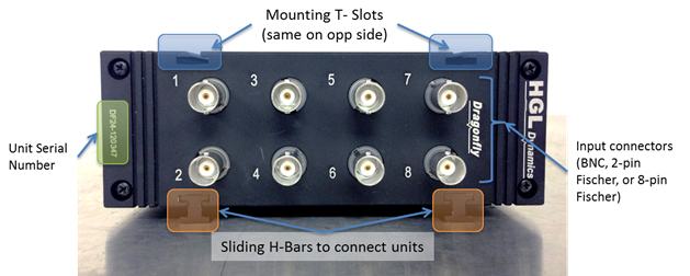
The Dragonfly8 module is presented in a rugged milled Aluminium chassis which is intended to provide good protection from shocks and vibration, dust and particulates.
In the stackable conditioning version the Dragonfly is provided with Fischer 8-pin analogue input connectors which allow all the functions of the conditioning to be used through physical wiring connections and software.
The rear panel of the Dragonfly8 module provide access to all the ancillary functions required for correct operation.
The 1000 BaseT Ethernet connector is provided in a waterproof form (as long as a mating waterproof Ethernet plug is used). This port can also be used to power the unit in Power Over Ethernet (POE) mode from supported switches such as the HGL DragonflySW module.
The Status LED panel (described more fully later) provides the only on board indication of the state of the Dragonfly. 4 LEDs are used for hardware state and 4 are used for Acquisition status information.
Dragonfly units are intended to be flexible and to be able to run with other modules ganged together. In order to maintain close synchronisation between modules (<4nS) HGL has developed an LVDS synchronisation system which uses 7-pin cables looping between each Dragonfly. More details on the use of these cables are provided later in this document.
The LVDS ports are labelled IN and OUT, this is important as LVDS is uni-directional. Care must be taken when setting up multiple Dragonfly units that the correct ports are used.
Optional GPS, IRIG and IEEE1588 synchronization interfaces are also available.
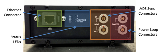
The Dragonfly can operate in two power supply modes (POE & DC). In the DC mode the nominal 12V dc power is input through one of the two power connectors indicated below. The other connector is used to loop power to the next Dragonfly in the chain.
There is no difference between the two connectors; power can be plugged into either.