
Trim Balance Pro
Introduction
Trim Balance Pro is an Interactive Software Package for the in-service balancing of rotating machinery including Aircraft engines, power generation Gas Turbines, Alternators and Pumps etc. Any rotating machine can be modeled providing it has at least one vibration monitoring device (accelerometer, displacement or velocity probe), a once per revolution signal and a means of calculating the vibration level and phase relative to the shaft marker. The HGL Dragonfly range of data acquisition and analysis products makes an ideal partner for this software package providing a cost effective and accurate means of calculating and recording the phase and amplitude of the signal.
The Software package provides an easy-to-use interface for computing the required masses and mass distribution to correct imbalance within the rotating machine, in addition it builds up a statistical database of results for each machine type encountered to speed the process of balancing similar machines in the future. This innovative software has a quick start-up and simple progression, with various options available to customise the appearance of the interface and interpretation of the data. The purpose of this user guide is to give an overview of the product and a detailed explanation of the tools and features available within.
The intention behind this application is that it should be used in parallel with Vibration Measurement system such as the HGL Dragonfly or any existing system capable of providing the phase and magnitude of the shaft vibration of the rotating machine. From this data, it can calibrate the mass-to-displacement ratio and compute a suitable distribution of mass to apply to the engine. This is provided for a given finite number of holes available at equal angles, where weight can be added. As is often the case in Engineering, theoretical results can transpire to be somewhat different to practical ones. The user can thus provide the true final displacement for future reference, or balance again if they prefer.
Capturing Data for Trim Balance Pro
TBP is an offline analysis tool. All data is captured using an external acquisition system such as those offered by our Hawk Acquisition Suite. Below are the basic steps used to capture the data from the HGL Acquisition Software.
Make sure the RT services are configured correctly. In software versions below 3.9, assistance from HGL support staff may be necessary. Here are the critical settings:
- Hawkeye Server phase calculations are to be lagging
- FFT size is set to 4k, This is done through the RealTimeSafety.ini file on the line "FFT Size (K)=". Set this to be "4"
- Tacho calculation window is 200 ms in RealTimeSpeedService.ini file
- Define the engine to have a 1/rev tachometer
- Assign the signal channel in the Hawk GUI configuration to reference the 1/rev tachometer channel
The tachometer channel, as implied above, needs to be a key phasor or any 1/rev signal. This provides the cleanest signal for calculating phase and, more crucially, gives a good physical reference point for locating the rotor for adding the balance weight. The signal used to measure the imbalance is preferably a proximeter probe or an accelerometer mounted on the shaft bearing in the direction for the primary vibration.
Setup the Hawkeye display to have a Polar-Bode plot with the reference signal configured to monitor the 1 EO response. It is beneficial to also have the tachometer displayed on an oscilloscope component on this same page.
Acquisition Steps:
- Slow crank the rotor until the key phase signal goes low. Number the potential weight locations on the rotor, numbering them opposite of the direction of rotation (e.g. so that the key phasor sensor would "see" each spot sequentially).
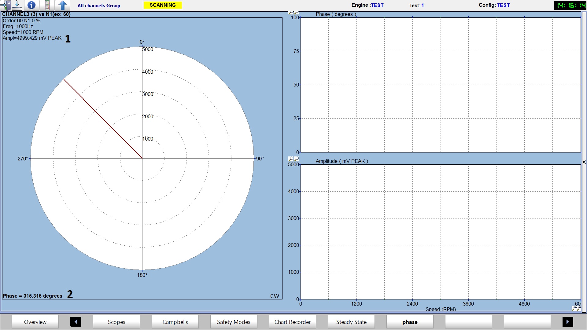
- Spin up the rotor as the base line response and enter initial Phase and Amplitude values into TBP in the Initial Calibration Section.
- The values you enter are found on the Polar-Bode plot in Hawkeye, as mentioned in the section above "Capturing Data for Trim Balance Pro."
- The information for the amplitude can be found next to 1 in the picture below. The information for the phase can be found next to 2 in the picture below.
- Slow crank (or rotate by hand) the rotor slowly until the key phasor signal goes low.
- Place a known balance weight and note the location (top dead center is recommended). Enter the information into the Calibration Weight Mass and Angle From Key Phasor sections in the Balance Calibration tab.
- Spin up the rotor again and enter the Phase and Amplitude values into TBP. Again, use the Hawkeye Polar/Bode plot to obtain this information.
- Slow crank the rotor again so that the key phasor signal goes low.
- Go to the Balance Results tab and click "Balance Engine." This will give you suggested balance weights and locations.
- Place the suggested balance weight in the location specified by TBP and remove the known calibration weight.
- Spin up the rotor again to verify the balance.

Using Trim Balance Pro Software
Start Up

When the Trim Balance Pro software is started the login screen is displayed. Once the user has logged in the main screen is displayed.

Main Screen
The different screens within the software are easily navigable from the main screen. Engines are quick to set up and multiple balances can be done on different parts of the database tree at once. All data is written to a central file that is constantly used by the software. This file is automatically loaded on start-up so the user can pick up where they left off. Alternatively they can export the data to another file and import a pre-existing one, if desired. Other options available include format editing for setting the number of decimal places used in results, and the colour scheme used in the program.
The information on the subsequent pages goes into the above features in more detail and explains the exact layout of the interface and how to use the software.
File Menu

Setting Up Engines:
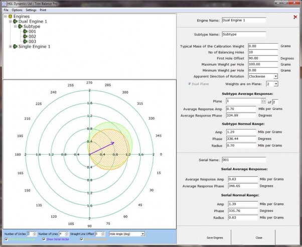
The first step when using Trim Balance Pro is to setup the engines. From the file menu select 'Set Up Engines,' if you are currently in a balance it will ask to close the current process. The screen below is the Engine Setup Screen. Balance information comes under an Engine-Subtype-Serial-Result hierarchy, which can be viewed in full on the results screen. This is designed to match real-world activities, with the dates and times of the balances recorded. If results do not match an actual balance that was performed they can be deleted. This collective information is important as Trim Balance Pro will compute the average response and normal range for results over the Serial and Subtype levels. This can be viewed in the setup screen, where new engines can also be added to the tree.
The screen that subsequently loads will be split into three portions. In the top left corner you will see the Engine List, which on first launch of the program will be empty. In the bottom left section you will see a graphical display containing concentric circles with fractions displayed across them. On the right side of the screen you will see a number of parameters to be entered; at first they will be disabled.

To create a new Engine right click on the Engines Tree in section 1 and select 'Add Engine' from the popup menu. Enter the name of the new engine. Next, the user will need to add a Subtype and Serial Number by right clicking on the engine it will be associated with and selecting "Add Subtype". Serial Numbers are added in the same fashion.
Subtypes are considered to be variations of the same type of engine, but can be different in terms of numbers of holes (points that mass can be added), and the kind of mass that can be applied (max allowed, typical value). Serials are completely identical engines of the same Subtype, but different instances - hence different serial numbers. Any of these nodes on the tree can be deleted by right clicking and selecting the 'Remove' option from the popup menu. This will also recursively delete all sub-nodes.
As you progress through each level you will see parts of the right hand display enable as appropriate to your part of the tree. The majority of the input information is in the Subtype portion and will thus apply to all Serials under it. In the picture above Section 2 shows the currently selected engine. Below that in section 3 we can see the selected sub-type where we can make changes to the config.
'Typical Mass of the Calibration Weight' - sets the default value for the calibration input when you perform balances, and must be less than Maximum Weight per Hole or auto adjustment will be applied. (This setting can be changed from the balance screen if a different weight is used)
'Number of Balancing Holes' - the number of points where weight can be added, the points are spaced evenly around the circle. The number has to be greater than 0.
'First Hole Offset' - number of degrees from the 0 degree point that the first balancing hole is located.
'Maximum Weight per Hole' - denotes the maximum amount of weight the software will add to the point to create a balance.
'Minimum Weight per Hole' - denotes the smallest amount of weight the software will add to a balancing hole.
'Apparent Direction of Rotation' - the direction the shaft is rotating
When all the selections are ready the user may save using the 'Save Engines' button. It should be noted that once saved the only fields that can be re-edited are the Typical Mass, Max, and Min settings.
Note that the Maximum Weight per Hole and Minimum Weight per Hole cannot be the same number, otherwise the software will not allow you to save the Engine.
Sections 4 and 5 are summary fields and the user cannot enter information into these sections. Once you have done a number of balances on different Serials, the statistics can be viewed from this screen. Every time a new result is saved Trim Balance Pro calculates a mean average of Response Amplitude and Phase, along with computing the Normal Range of these values, across the Serial and Subtype categories. When you click on a Subtype/Serial, the range(s) is/are plotted on the graph. The most recent response vector for the Serial is also plotted. Reliable engines will have similar Serial and Subtype Ranges, and the vector should be pointing inside the Serial range if the latest response is reliable.
New Balance
When the ‘New Balance’ option is selected the ‘Select Engine’ form is displayed.
Select Engine Form
Each balance you do is applied to a particular Serial, i.e. one particular existing engine. From the ‘Select Engine’ form you must select the Engine and then the Subtype, before the Serial for your chosen balance. You can then select OK to start the balance. The ‘Initial Calibration’ screen will load. Alternatively you can select Set Up to close the box and open the Set Up Engines window.

Initial Calibration Screen
The first stage in performing a new balance is setting the initial calibration, or displacement of the shaft. At the top of the screen you will see that we are in the first of three tabs; each tab along is a progression to the next stage of the balance. In this example we are dealing with a dual plane case, so there are two measurements of displacement, which are distinguished by the lower set of tabs. In the single plane case the Plane tabs would not be present.

Once you have the measurement values of amplitude and phase for the rotating machine, these can be entered in the “Initial Amplitude” and “Initial Phase” Boxes and will appear visually on the graph on the right hand side of the screen. Underneath these boxes there are two more boxes for “Desired Amplitude” and “Desired Phase”. These can be ignored if the Engine is to be balanced at equilibrium, but if the Engine is to be biased at a specific amplitude and phase then those values should be entered here. Desired Phase is disabled if Desired Amplitude is set to zero, as this value becomes redundant.
On the first balance of an engine, the table of mass values for each hole will be empty as no mass has been applied yet. This also means that the two tick boxes at the top are disabled. ‘Keep Old Masses’ will ensure that any previously added masses can only be increased, not decreased. ‘Automatic Calibration’ will use the previous session’s calibration stage to perform the balance. Ticking this box would mean that the next tab, Balance Calibration, would be disabled, as this stage would become unnecessary.
Balance Calibration Screen
Balance Calibration refers to the determination of a response amplitude and phase for an added weight mass and angle. This allows the software to determine where masses need to be added to correct the initial displacement. You must add a mass to a hole on the physical engine and take a measurement of the new displacement. Enter this information in the displayed boxes. The calibration weight should then be removed from the physical engine. 
As you progress through the balance process, you will see vectors being added to the graph. There is a key to the vectors at the bottom of the graph, and they can be removed and added as you wish, with the appropriate tick boxes shown.
On the next page we can see the final tab, Balance Results. Initially the Weight Amplitude and Weight Phase values are displayed, showing the effective amplitude and phase supplied by the calibration weight. Had we used the calibration from a previous session, the response values would also be initially displayed. Clicking Balance Engine performs the balance calculations, and all remaining values are unveiled.
Balance Results Screen
The required masses are added. This is done by calculating the angle where the mass should ideally be placed, and if necessary, splitting the mass between two neighbouring holes to achieve the same effect. Added mass is shown in green here. Vectors are added for response and correction. 
The Pred. Final Amplitude should be equivalent to the Desired Amplitude as the point of the calculations is to eliminate any unwanted displacement. If it is not then this is because the maximum allowed weight is not great enough to accommodate the required change, and you should consider changing this in the engine setup. The Pred. Final Phase should also ideally match the Desired Phase, unless the Desired Amplitude was zero, in which case phase is unimportant. For the dual plane case, the balancing is only applied to the plane with the weights on and the result of the other plane is merely the application of the same weights. The corrected plane is automatically selected upon clicking the Balance Engine button and you can check which plane this is in the information above the graph. Pred. Final Phase is irrelevant in terms of whether or not the engine is balanced, but is given for reference.
Actual Final Amplitude and Actual Final Phase are parameters that need to be filled in; the suggested weights should be added to the physical engine, the displacement of the shaft checked again and the amplitude and phase measured should be entered here.
If you need to balance again you can go back to any tab and change the inputs and balance again. Once you are happy with the results you can click Accept Results to save these displayed values, along with a log of the date and time. Once saved you can either leave the session or perform another balance.
Note also that the vectors on the graph are scaled according to the largest one that is displayed. Hence removing larger vectors will cause a zoom in on the smaller ones, such as the response vector.
Close All Open Balances
To close all open balances, click on the red cross in the top corner to exit without saving at any point.
View Engine Results
The screen that loads contains the engine tree, with results added under serials, in the top left corner, a table of information that is filled out by the selected result in the bottom left and another vector graph on the right side.
The result node on the tree is represented by the date and time it was performed. The result data is split into calibration mass values and displacement values, the latter having plane tabs if necessary. Results can be deleted by pressing Delete Result. The changes only become permanent when Commit Changes is pressed, or you agree to commit when you exit by pressing the red cross.
 Options Menu
These options lets you read/write all the values for the selected unit;
 Angle Unit: Degrees or Radians.
Amplitude Unit: Mils or Microns.
Mass Unit: Grams or Ounces.
Settings Menu

Pressing the green cross next to the drop down menu will copy the previous scheme to a new one, and you can then edit the colours by double clicking on the existing colour given for each aspect. Browse the tabs to find all the different aspects. The red cross can be used to delete a scheme. Any existing scheme can also be edited. Press OK to save all changes.

Format Settings
This option produces a window for specifying the truncation of floating point numbers for display purposes. The default setting is two decimal places and can be thirteen maximum.

Save Engine/Balance Data to File
This option opens a dialog for saving the current engines, results and statistics to another file.
Load Engine/Balance Data from File
This option deletes the current engines, results and statistics and opens a dialog for selecting a file to load new ones from. It is recommended you use the Save Engine/Balance Data To File option first, if you don’t wish to lose the old data.
Print Menu

Print Screen: This prints a screenshot of the current display.
Print Options: This allows you to change the current printer settings.